-
1 (mechanical) switch
выключатель (контактный)
Контактный коммутационный аппарат, способный включать, проводить и отключать токи в нормальных условиях, в том числе при оговоренных рабочих перегрузках, а также в течение установленного времени проводить ток в оговоренных аномальных условиях, например при коротком замыкании.
МЭК 60050(441-14-10)
Примечание. Выключатель может быть способен включать, но не отключать ток короткого замыкания.
[ ГОСТ Р 50030. 1-2000 ( МЭК 60947-1-99)]EN
(mechanical) switch
a mechanical switching device capable of making, carrying and breaking currents under normal circuit conditions which may include specified operating overload conditions and also carrying for a specified time currents under specified abnormal circuit conditions such as those of short circuit
NOTE – A switch may be capable of making but not breaking short-circuit currents.
[IEV number 441-14-10]FR
interrupteur (mécanique)
appareil mécanique de connexion capable d'établir, de supporter et d'interrompre des courants dans les conditions normales du circuit y compris éventuellement les conditions spécifiées de surcharge en service, ainsi que de supporter pendant une durée spécifiée des courants dans des conditions anormales spécifiées du circuit telles que celles du court-circuit
NOTE – Un interrupteur peut être capable d'établir des courants de court-circuit mais n'est pas capable de les couper
[IEV number 441-14-10]Недопустимые, нерекомендуемые
Тематики
- выключатель, переключатель
EN
DE
FR
Англо-русский словарь нормативно-технической терминологии > (mechanical) switch
-
2 mechanical rating
степень защиты
Способ защиты, обеспечиваемый оболочкой от доступа к опасным частям, попадания внешних твердых предметов и (или) воды и проверяемый стандартными методами испытаний.
[ ГОСТ 14254-96( МЭК 529-89)]
степень защиты, обеспечиваемая оболочкой (IP)
Числовые обозначения после кода IP, которые в соответствии с МЭК 60529 [12] характеризуют оболочку электрооборудования, обеспечивающую:
- защиту персонала от прикасания или доступа к находящимся под напряжением или движущимся частям (за исключением гладких вращающихся валов и т.п.), расположенным внутри оболочки;
- защиту электрооборудования от проникания в него твердых посторонних тел и,
- если указано в обозначении, защиту электрооборудования от вредного проникания воды.
[ ГОСТ Р МЭК 60050-426-2006]EN
degree of protection of enclosure
IP (abbreviation)
numerical classification according to IEC 60529 preceded by the symbol IP applied to the enclosure of electrical apparatus to provide:
– protection of persons against contact with, or approach to, live parts and against contact with moving parts (other than smooth rotating shafts and the like) inside the enclosure,
– protection of the electrical apparatus against ingress of solid foreign objects, and
– where indicated by the classification, protection of the electrical apparatus against harmful ingress of water
[IEV number 426-04-02 ]FR
degré de protection procuré par une enveloppe
IP (abréviation)
classification numérique selon la CEI 60529, précédée du symbole IP, appliquée à une enveloppe de matériel électrique pour apporter:
– une protection des personnes contre tout contact ou proximité avec des parties actives et contre tout contact avec une pièce mobile (autre que les roulements en faible rotation) à l'intérieur d'une enveloppe
– une protection du matériel électrique contre la pénétration de corps solide étrangers, et
– selon l’indication donnée par la classification, une protection du matériel électrique contre la pénétration dangereuse de l’eau
[IEV number 426-04-02 ]Элементы кода IP и их обозначения по ГОСТ 14254-96( МЭК 529-89)
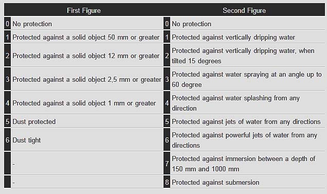
Цифры кода IP
Значение для защиты оборудования от проникновения внешних твердых предметов
Значение для защиты людей от доступа к опасным частям
Первая характеристическая цифра
0
Нет защиты
Нет защиты
1
диаметром ≥ 50 мм
тыльной стороной руки
2
диаметром ≥ 12,5 мм
пальцем
3
диаметром ≥ 2,5 мм
инструментом
4
диаметром ≥ 1,0 мм
проволокой
5
пылезащищенное
проволокой
6
пыленепроницаемое
проволокой
От вредного воздействия в результате проникновения воды
Вторая характеристическая цифра
0
Нет защиты
-
1
Вертикальное каплепадение
2
Каплепадение (номинальный угол 15°)
3
Дождевание
4
Сплошное обрызгивание
5
Действие струи
6
Сильное действие струи
7
Временное непродолжительное погружение
8
Длительное погружение
Дополнительная буква (при необходимости)
-
От доступа к опасным частям
A
тыльной стороной руки
B
пальцем
C
инструментом
проволокой
Вспомогательная буква (при необходимости)
Вспомогательная информация относящаяся к:
-
H
высоковольтным аппаратам
M
состоянию движения во время испытаний защиты от воды
S
состоянию неподвижности во время испытаний защиты от воды
W
Требования в части стойкости оболочек и электрооборудования в целом к климатическим, механическим внешним воздействующим факторам (ВВФ) и специальным средам (кроме проникновения внешних твердых предметов и воды) установлены вне рамок настоящего стандарта.
Параллельные тексты EN-RU
The code IP indicates the degrees of protection provided by an enclosure against access to hazardous parts, ingress of solid foreign objects and ingress of water.
The degree of protection of an enclosure is identified, in compliance with the specifications of the Standard IEC 60529, by the code letters IP (International Protection) followed by two numerals and two additional letters.
The first characteristic numeral indicates the degree of protection against ingress of solid foreign objects and against contact of persons with hazardous live parts inside the enclosure.
The second characteristic numeral indicates the degree of protection against ingress of water with harmful effects.
[ABB]Код IP обозначает степень защиты, обеспечиваемую оболочкой от попадания внутрь твердых посторонних предметов и воды.
Степень защиты оболочки обозначается в соответствии со стандартом МЭК 60529 буквенным обозначением IP (International Protection, т. е. Международная защита) после которого следуют две цифры, к которым в некоторых случаях добавляются еще две буквы.
Первая характеристическая цифра обозначает степень защиты от проникновения твердых посторонних предметов и от контакта людей с находящимися внутри оболочки опасными токоведущими частями.
Вторая характеристическая цифра обозначает степень защиты оболочки с точки зрения вредного воздействия, оказываемого проникновением воды.
[Перевод Интент]The protection of enclosures against ingress of dirt or against the ingress of water is defined in IEC529 (BSEN60529:1991). Conversely, an enclosure which protects equipment against ingress of particles will also protect a person from potential hazards within that enclosure, and this degree of protection is also defined as a standard.
The degrees of protection are most commonly expressed as ‘IP’ followed by two numbers, e.g. IP65, where the numbers define the degree of protection. The first digit shows the extent to which the equipment is protected against particles, or to which persons are protected from enclosed hazards. The second digit indicates the extent of protection against water.
The wording in the table is not exactly as used in the standards document, but the dimensions are accurateIP Degree of Protection according to EN/IEC 60529
Correlations between IP (IEC) and NEMA 250 standards
IP10 -> NEMA 1
IP11 -> NEMA 2
IP54 -> NEMA 3 R
IP52 -> NEMA 5-12-12 K
IP54 -> NEMA 3-3 S
IP56 -> NEMA 4-4 X
IP67 -> NEMA 6-6 P[ http://electrical-engineering-portal.com/ip-protection-degree-iec-60529-explained]
Тематики
- безопасность машин и труда в целом
- электробезопасность
- электротехника, основные понятия
Действия
- степень защиты
- степень защиты, обеспечиваемая оболочкой
- степень защиты, обеспечиваемая оболочкой (код IP)
EN
- amount of protection
- degree of protection IP
- degree of protection of an enclosure
- degree of protection of enclosure
- degree of protection provided by enclosure
- enclosure rating
- ingress protection rating
- IP
- IP degree of protection,
- IP rating
- IP Sealing Specification
- IP security
- IPSec
- level of protection
- mechanical rating
- protection
- protection index
- protection rating
DE
- IP-Schutzgrad, m
- Schutzart des Gehäuses, f
FR
Англо-русский словарь нормативно-технической терминологии > mechanical rating
-
3 mechanical me·chani·cal adj
[mɪ'kænɪk(ə)l](also) fig meccanico (-a) -
4 Mechanical, pneumatic and hydraulic engineering
See also: INDEX BY SUBJECT AREA[br]Clement, JosephDu ShiDu YuGongshu PanLi BingMa JunMurdock, WilliamSomerset, EdwardBiographical history of technology > Mechanical, pneumatic and hydraulic engineering
-
5 contact (of a mechanical switching device)
контакт (1)
-
[IEV number 151-12-15 ]
контакт (контактного коммутационного аппарата)
Токопроводящие части, предназначенные для установления непрерывности цепи при их соприкосновении и в результате их движения относительно друг друга в процессе оперирования размыкающие или замыкающие цепь либо, если это шарнирные или скользящие контакты, поддерживающие непрерывность цепи.
МЭК 60050(441-15-05).
[ ГОСТ Р 50030. 1-2000 ( МЭК 60947-1-99)]
контакт
Токоведущая часть аппарата, которая во время операции размыкает и замыкает цепь, или в случае скользящих или шарнирных контактов сохраняет непрерывность цепи
[РД 34.45-51.300-97]EN
contact (1)
set of conductive elements for establishing electric circuit continuity when they touch each other and which, due to their relative motion during an operation, open or close an electric circuit or, in the case of some hinged or sliding elements, maintain circuit continuity
NOTE – See also the concept "electric contact" in 151-12-03.
[IEV number 151-12-15 ]
contact (of a mechanical switching device)
conductive parts designed to establish circuit continuity when they touch and which, due to their relative motion during an operation, open or close a circuit or, in the case of hinged or sliding contacts, maintain circuit continuity
[IEV number 441-15-05]FR
contact (1), m
ensemble d'éléments conducteurs destinés à établir la continuité d'un circuit électrique lorsqu'ils se touchent et qui, par leur mouvement relatif pendant la manœuvre, ouvrent ou ferment un circuit électrique ou, dans le cas de certains éléments pivotants ou glissants, maintiennent la continuité du circuit
NOTE – Voir aussi le concept "contact électrique" en 151-12-03.
[IEV number 151-12-15 ]
contact (d'un appareil de connexion)
pièces conductrices destinées à établir la continuité d'un circuit lorsqu'elles se touchent et qui, par leur mouvement relatif pendant la manoeuvre, ouvrent et ferment un circuit ou, dans le cas de contacts pivotants ou glissants, maintiennent la continuité du circuit
[IEV number 441-15-05]2
контакт (2)
-
[IEV number 151-12-16]EN
contact (2)
conductive element intended to make an electric contact
[IEV number 151-12-16]FR
contact (2), m
élément conducteur destiné à établir un contact électrique
[IEV number 151-12-16]Тематики
- контакт
- электротехника, основные понятия
Действия
- замыкать контакт
- контакт коммутирует цепь (аппарата, нагрузки...)
- НДП - закрывать контакт
- НДП - открывать контакт
- НДП - разъединять контакт
- размыкать контакт
EN
DE
FR
Англо-русский словарь нормативно-технической терминологии > contact (of a mechanical switching device)
-
6 beam flange
-
7 girder flange
-
8 shaping
-
9 Bond, George Meade
SUBJECT AREA: Mechanical, pneumatic and hydraulic engineering[br]b. 17 July 1852 Newburyport, Massachusetts, USAd. 6 January 1935 Hartford, Connecticut, USA[br]American mechanical engineer and metrologist, co-developer of the Rogers- Bond Comparator.[br]After leaving school at the age of 17, George Bond taught in local schools for a few years before starting an apprenticeship in a machine shop in Grand Rapids, Michigan. He then worked as a machinist with Phoenix Furniture Company in that city until his savings permitted him to enter the Stevens Institute of Technology at Hoboken, New Jersey, in 1876. He graduated with the degree of Mechanical Engineer in 1880. In his final year he assisted William A.Rogers, Professor of Astronomy at Harvard College Observatory, Cambridge, Massachusetts, in the design of a comparator for checking standards of length. In 1880 he joined the Pratt \& Whitney Company, Hartford, Connecticut, and was Manager of the Standards and Gauge Department from then until 1902. During this period he developed cylindrical, calliper, snap, limit, thread and other gauges. He also designed the Bond Standard Measuring Machine. Bond was elected a member of the American Society of Mechanical Engineers in 1881 and of the American Society of Civil Engineers in 1887, and served on many of their committees relating to standards and units of measurement.[br]Principal Honours and DistinctionsVice-President, American Society of Mechanical Engineers 1908–10. Honorary degrees of DEng, Stevens Institute of Technology 1921, and MSc, Trinity College, Hartford, 1927.Bibliography1881. "Standard measurements", Transactions of the American Society of Mechanical Engineers 2:81.1882. "A standard gauge system", Transactions of the American Society of MechanicalEngineers 3:122.1886, "Standard pipe and pipe threads", Transactions of the American Society of Mechanical Engineers 7:311.1887. Standards of Length and Their Practical Application, Hartford.Further Reading"Report of the Committee on Standards and Gauges", 1883, Transactions of the American Society of Mechanical Engineers 4:21–9 (describes the Rogers-Bond Comparator).RTS -
10 Gresley, Sir Herbert Nigel
[br]b. 19 June 1876 Edinburgh, Scotlandd. 5 April 1941 Hertford, England[br]English mechanical engineer, designer of the A4-class 4–6–2 locomotive holding the world speed record for steam traction.[br]Gresley was the son of the Rector of Netherseale, Derbyshire; he was educated at Marlborough and by the age of 13 was skilled at making sketches of locomotives. In 1893 he became a pupil of F.W. Webb at Crewe works, London \& North Western Railway, and in 1898 he moved to Horwich works, Lancashire \& Yorkshire Railway, to gain drawing-office experience under J.A.F.Aspinall, subsequently becoming Foreman of the locomotive running sheds at Blackpool. In 1900 he transferred to the carriage and wagon department, and in 1904 he had risen to become its Assistant Superintendent. In 1905 he moved to the Great Northern Railway, becoming Superintendent of its carriage and wagon department at Doncaster under H.A. Ivatt. In 1906 he designed and produced a bogie luggage van with steel underframe, teak body, elliptical roof, bowed ends and buckeye couplings: this became the prototype for East Coast main-line coaches built over the next thirty-five years. In 1911 Gresley succeeded Ivatt as Locomotive, Carriage \& Wagon Superintendent. His first locomotive was a mixed-traffic 2–6–0, his next a 2–8–0 for freight. From 1915 he worked on the design of a 4–6–2 locomotive for express passenger traffic: as with Ivatt's 4 4 2s, the trailing axle would allow the wide firebox needed for Yorkshire coal. He also devised a means by which two sets of valve gear could operate the valves on a three-cylinder locomotive and applied it for the first time on a 2–8–0 built in 1918. The system was complex, but a later simplified form was used on all subsequent Gresley three-cylinder locomotives, including his first 4–6–2 which appeared in 1922. In 1921, Gresley introduced the first British restaurant car with electric cooking facilities.With the grouping of 1923, the Great Northern Railway was absorbed into the London \& North Eastern Railway and Gresley was appointed Chief Mechanical Engineer. More 4–6– 2s were built, the first British class of such wheel arrangement. Modifications to their valve gear, along lines developed by G.J. Churchward, reduced their coal consumption sufficiently to enable them to run non-stop between London and Edinburgh. So that enginemen might change over en route, some of the locomotives were equipped with corridor tenders from 1928. The design was steadily improved in detail, and by comparison an experimental 4–6–4 with a watertube boiler that Gresley produced in 1929 showed no overall benefit. A successful high-powered 2–8–2 was built in 1934, following the introduction of third-class sleeping cars, to haul 500-ton passenger trains between Edinburgh and Aberdeen.In 1932 the need to meet increasing road competition had resulted in the end of a long-standing agreement between East Coast and West Coast railways, that train journeys between London and Edinburgh by either route should be scheduled to take 8 1/4 hours. Seeking to accelerate train services, Gresley studied high-speed, diesel-electric railcars in Germany and petrol-electric railcars in France. He considered them for the London \& North Eastern Railway, but a test run by a train hauled by one of his 4–6–2s in 1934, which reached 108 mph (174 km/h), suggested that a steam train could better the railcar proposals while its accommodation would be more comfortable. To celebrate the Silver Jubilee of King George V, a high-speed, streamlined train between London and Newcastle upon Tyne was proposed, the first such train in Britain. An improved 4–6–2, the A4 class, was designed with modifications to ensure free running and an ample reserve of power up hill. Its streamlined outline included a wedge-shaped front which reduced wind resistance and helped to lift the exhaust dear of the cab windows at speed. The first locomotive of the class, named Silver Link, ran at an average speed of 100 mph (161 km/h) for 43 miles (69 km), with a maximum speed of 112 1/2 mph (181 km/h), on a seven-coach test train on 27 September 1935: the locomotive went into service hauling the Silver Jubilee express single-handed (since others of the class had still to be completed) for the first three weeks, a round trip of 536 miles (863 km) daily, much of it at 90 mph (145 km/h), without any mechanical troubles at all. Coaches for the Silver Jubilee had teak-framed, steel-panelled bodies on all-steel, welded underframes; windows were double glazed; and there was a pressure ventilation/heating system. Comparable trains were introduced between London Kings Cross and Edinburgh in 1937 and to Leeds in 1938.Gresley did not hesitate to incorporate outstanding features from elsewhere into his locomotive designs and was well aware of the work of André Chapelon in France. Four A4s built in 1938 were equipped with Kylchap twin blast-pipes and double chimneys to improve performance still further. The first of these to be completed, no. 4468, Mallard, on 3 July 1938 ran a test train at over 120 mph (193 km/h) for 2 miles (3.2 km) and momentarily achieved 126 mph (203 km/h), the world speed record for steam traction. J.Duddington was the driver and T.Bray the fireman. The use of high-speed trains came to an end with the Second World War. The A4s were then demonstrated to be powerful as well as fast: one was noted hauling a 730-ton, 22-coach train at an average speed exceeding 75 mph (120 km/h) over 30 miles (48 km). The war also halted electrification of the Manchester-Sheffield line, on the 1,500 volt DC overhead system; however, anticipating eventual resumption, Gresley had a prototype main-line Bo-Bo electric locomotive built in 1941. Sadly, Gresley died from a heart attack while still in office.[br]Principal Honours and DistinctionsKnighted 1936. President, Institution of Locomotive Engineers 1927 and 1934. President, Institution of Mechanical Engineers 1936.Further ReadingF.A.S.Brown, 1961, Nigel Gresley, Locomotive Engineer, Ian Allan (full-length biography).John Bellwood and David Jenkinson, Gresley and Stanier. A Centenary Tribute (a good comparative account).See also: Bulleid, Oliver Vaughan SnellPJGRBiographical history of technology > Gresley, Sir Herbert Nigel
-
11 Guest, James John
SUBJECT AREA: Mechanical, pneumatic and hydraulic engineering[br]b. 24 July 1866 Handsworth, Birmingham, Englandd. 11 June 1956 Virginia Water, Surrey, England[br]English mechanical engineer, engineering teacher and researcher.[br]James John Guest was educated at Marlborough in 1880–4 and at Trinity College, Cambridge, graduating as fifth wrangler in 1888. He received practical training in several workshops and spent two years in postgraduate work at the Engineering Department of Cambridge University. After working as a draughtsman in the machine-tool, hydraulic and crane departments of Tangyes Ltd at Birmingham, he was appointed in 1896 Assistant Professor of Engineering at McGill University in Canada. After a short time he moved to the Polytechnic Institute at Worcester, Massachusetts, where he was for three years Professor of Mechanical Engineering and Head of the Engineering Department. In 1899 he returned to Britain and set up as a consulting engineer in Birmingham, being a partner in James J.Guest \& Co. For the next fifteen years he combined this work with research on grinding phenomena. He also developed a theory of grinding which he first published in a paper at the British Association for the Advancement of Science in 1914 and elaborated in a paper to the Institution of Mechanical Engineers and in his book Grinding Machinery (1915). During the First World War, in 1916–17, he was in charge of inspection in the Staffordshire and Shropshire Area, Ministry of Munitions. In 1917 he returned to teaching as Reader in Graphics and Structural Engineering at University College London. His final appointment was about 1923 as Professor of Mechanical and Electrical Engineering, Artillery College, Woolwich, which later became the Military College of Science.He carried out research on the strength of materials and contributed many articles on the subject to the technical press. He originated Guest's Law for a criterion of failure of materials under combined stresses, first published in 1900. He was a Member of the Institution of Mechanical Engineers in 1900–6 and from 1919 and contributed to their proceedings in many discussions and two major papers.[br]BibliographyOf many publications by Guest, the most important are: 1900, "Ductile materials under combined stress", Proceedings of the Physical Society 17:202.1915, Grinding Machinery, London.1915, "Theory of grinding, with reference to the selection of speeds in plain and internal work", Proceedings of the Institution of Mechanical Engineers 89:543.1917. "Torsional hysteresis of mild steel", Proceedings of the Royal Society A93:313.1918. with F.C.Lea, "Curved beams", Proceedings of the Royal Society A95:1. 1930, "Effects of rapidly acting stress", Proceedings of the Institution of MechanicalEngineers 119:1,273.RTS -
12 Bilgram, Hugo
SUBJECT AREA: Mechanical, pneumatic and hydraulic engineering[br]b. 13 January 1847 Memmingen, Bavaria, Germanyd. 27 August 1932 Moylan, Pennsylvania, USA[br]German (naturalized American) mechanical engineer, inventor of bevel-gear generator and economist.[br]Hugo Bilgram studied mechanical engineering at the Augsburg Maschinenbau Schule and graduated in 1865. He worked as a machinist and draughtsman for several firms in Germany before going to the United States in 1869.In America he first worked for L.B.Flanders Company and Southwark Foundry \& Machine Company in Philadelphia, designing instruments and machines. In the 1870s he also assisted in an evening class in drawing at The Franklin Institute. He devised the Bilgram Valve Diagram for analysing the action of steam engine slide valves and he developed a method of drawing accurate outlines of gear teeth. This led him to design a machine for cutting the teeth of gear wheels, particularly bevel wheels, which he patented in 1884. He was in charge of the American branch of Brehmer Brothers Company from 1879 and in 1884 became the sole owner of the company, which was later incorporated as the Bilgram Machine Works. He was responsible for several other inventions and developments in gear manufacture.Bilgram was a member of the Franklin Institute, the American Academy of Political and Social Science, the Philadelphia Technische Verein and the Philadelphia Engineer's Club, and was elected a member of the American Society of Mechanical Engineers in 1885. He was also an amateur botanist, keenly interested in microscopic work.[br]Principal Honours and DistinctionsFranklin Institute Elliott Cresson Gold Medal. City of Philadelphia John Scott Medal.BibliographyHugo Bilgram was granted several patents and was the author of: 1877, Slide Valve Gears.1889, Involuntary Idleness.1914, The Cause of Business Depression.1928, The Remedy for Overproduction and Unemployment.Further ReadingRobert S.Woodbury, 1958, History of the Gear-cutting Machine, Cambridge, Mass, (describes Bilgram's bevel-gear generating machine).RTS -
13 Pratt, Francis Ashbury
[br]b. 15 February 1827 Woodstock, Vermont, USAd. 10 February 1902 Hartford, Connecticut, USA[br]American mechanical engineer and machine-tool manufacturer.[br]Francis A.Pratt served an apprenticeship as a machinist with Warren Aldrich, and on completing it in 1848 he entered the Gloucester Machine Works as a journeyman machinist. From 1852 to 1854 he worked at the Colt Armory in Hartford, Connecticut, where he met his future partner, Amos Whitney. He then became Superintendent of the Phoenix Iron Works, also at Hartford and run by George S.Lincoln \& Company. While there he designed the well-known "Lincoln" miller, which was first produced in 1855. This was a development of the milling machine built by Robbins \& Lawrence and designed by F.W. Howe, and incorporated a screw drive for the table instead of the rack and pinion used in the earlier machine.Whitney also moved to the Phoenix Iron Works, and in 1860 the two men started in a small way doing machine work on their own account. In 1862 they took a third partner, Monroe Stannard, and enlarged their workshop. The business continued to expand, but Pratt and Whitney remained at the Phoenix Iron Works until 1864 and in the following year they built their first new factory. The Pratt \& Whitney Company was incorporated in 1869 with a capital of $350,000, F.A.Pratt being elected President. The firm specialized in making machine tools and tools particularly for the armament industry. In the 1870s Pratt made no less than ten trips to Europe gaining orders for equipping armouries in many different countries. Pratt \& Whitney was one of the leading firms developing the system of interchangeable manufacture which led to the need to establish national standards of measurement. The Rogers-Bond Comparator, developed with the backing of Pratt \& Whitney, played an important part in the establishment of these standards, which formed the basis of the gauges of many various types made by the firm. Pratt remained President of the company until 1898, after which he served as their Consulting Engineer for a short time before retiring from professional life. He was granted a number of patents relating to machine tools. He was a founder member of the American Society of Mechanical Engineers in 1880 and was elected a vice-president in 1881. He was an alderman of the city of Hartford.[br]Principal Honours and DistinctionsVice-President, American Society of Mechanical Engineers 1881.Further ReadingJ.W.Roe, 1916, English and American Tool Builders, New Haven; reprinted 1926, New York, and 1987, Bradley, 111. (describes the origin and development of the Pratt \& Whitney Company).RTS -
14 Smith, Oberlin
[br]b. 22 March 1840 Cincinnati, Ohio, USAd. 18 July 1926[br]American mechanical engineer, pioneer in experiments with magnetic recording.[br]Of English descent, Smith embarked on an education in mechanical engineering, graduating from West Jersey Academy, Bridgeton, New Jersey, in 1859. In 1863 he established a machine shop in Bridgeton, New Jersey, that became the Ferracute Machine Company in 1877, eventually specializing in the manufacture of presses for metalworking. He seems to have subscribed to design principles considered modern even in the 1990s, "always giving attention to the development of artistic form in combination with simplicity, and with massive strength where required" (bibliographic reference below). He was successful in his business, and developed and patented a large number of mechanical constructions.Inspired by the advent of the phonograph of Edison, in 1878 Smith obtained the tin-foil mechanical phonograph, analysed its shortcomings and performed some experiments in magnetic recording. He filed a caveat in the US Patent Office in order to be protected while he "reduced the invention to practice". However, he did not follow this trail. When there was renewed interest in practical sound recording and reproduction in 1888 (the constructions of Berliner and Bell \& Tainter), Smith published an account of his experiments in the journal Electrical World. In a corrective letter three weeks later it is clear that he was aware of the physical requirements for the interaction between magnetic coil and magnetic medium, but his publications also indicate that he did not as such obtain reproduction of recorded sound.Smith did not try to develop magnetic recording, but he felt it imperative that he be given credit for conceiving the idea of it. When accounts of Valdemar Poulsen's work were published in 1900, Smith attempted to prove some rights in the invention in the US Patent Office, but to no avail.He was a highly respected member of both his community and engineering societies, and in later life became interested in the anti-slavery cause that had also been close to the heart of his parents, as well as in the YMCA movement and in women's suffrage.[br]BibliographyApart from numerous technical papers, he wrote the book Press Working of Metals, 1896. His accounts on the magnetic recording experiments were "Some possible forms of phonograph", Electrical World (8 September 1888): 161 ff, and "Letter to the Editor", Electrical World (29 September 1888): 179.Further ReadingF.K.Engel, 1990, Documents on the Invention of Magnetic Recording in 1878, New York: Audio Engineering Society, Reprint no. 2,914 (G2) (a good overview of the material collected by the Oberlin Smith Society, Bridgeton, New Jersey, in particular as regards the recording experiments; it is here that it is doubted that Valdemar Poulsen developed his ideas independently).GB-N -
15 Adamson, Daniel
SUBJECT AREA: Mechanical, pneumatic and hydraulic engineering, Metallurgy, Steam and internal combustion engines[br]b. 1818 Shildon, Co. Durham, Englandd. January 1890 Didsbury, Manchester, England[br]English mechanical engineer, pioneer in the use of steel for boilers, which enabled higher pressures to be introduced; pioneer in the use of triple-and quadruple-expansion mill engines.[br]Adamson was apprenticed between 1835 and 1841 to Timothy Hackworth, then Locomotive Superintendent on the Stockton \& Darlington Railway. After this he was appointed Draughtsman, then Superintendent Engineer, at that railway's locomotive works until in 1847 he became Manager of Shildon Works. In 1850 he resigned and moved to act as General Manager of Heaton Foundry, Stockport. In the following year he commenced business on his own at Newton Moor Iron Works near Manchester, where he built up his business as an iron-founder and boilermaker. By 1872 this works had become too small and he moved to a 4 acre (1.6 hectare) site at Hyde Junction, Dukinfield. There he employed 600 men making steel boilers, heavy machinery including mill engines fitted with the American Wheelock valve gear, hydraulic plant and general millwrighting. His success was based on his early recognition of the importance of using high-pressure steam and steel instead of wrought iron. In 1852 he patented his type of flanged seam for the firetubes of Lancashire boilers, which prevented these tubes cracking through expansion. In 1862 he patented the fabrication of boilers by drilling rivet holes instead of punching them and also by drilling the holes through two plates held together in their assembly positions. He had started to use steel for some boilers he made for railway locomotives in 1857, and in 1860, only four years after Bessemer's patent, he built six mill engine boilers from steel for Platt Bros, Oldham. He solved the problems of using this new material, and by his death had made c.2,800 steel boilers with pressures up to 250 psi (17.6 kg/cm2).He was a pioneer in the general introduction of steel and in 1863–4 was a partner in establishing the Yorkshire Iron and Steel Works at Penistone. This was the first works to depend entirely upon Bessemer steel for engineering purposes and was later sold at a large profit to Charles Cammell \& Co., Sheffield. When he started this works, he also patented improvements both to the Bessemer converters and to the engines which provided their blast. In 1870 he helped to turn Lincolnshire into an important ironmaking area by erecting the North Lincolnshire Ironworks. He was also a shareholder in ironworks in South Wales and Cumberland.He contributed to the development of the stationary steam engine, for as early as 1855 he built one to run with a pressure of 150 psi (10.5 kg/cm) that worked quite satisfactorily. He reheated the steam between the cylinders of compound engines and then in 1861–2 patented a triple-expansion engine, followed in 1873 by a quadruple-expansion one to further economize steam. In 1858 he developed improved machinery for testing tensile strength and compressive resistance of materials, and in the same year patents for hydraulic lifting jacks and riveting machines were obtained.He was a founding member of the Iron and Steel Institute and became its President in 1888 when it visited Manchester. The previous year he had been President of the Institution of Civil Engineers when he was presented with the Bessemer Gold Medal. He was a constant contributor at the meetings of these associations as well as those of the Institution of Mechanical Engineers. He did not live to see the opening of one of his final achievements, the Manchester Ship Canal. He was the one man who, by his indomitable energy and skill at public speaking, roused the enthusiasm of the people in Manchester for this project and he made it a really practical proposition in the face of strong opposition.[br]Principal Honours and DistinctionsPresident, Institution of Civil Engineers 1887.President, Iron and Steel Institute 1888. Institution of Civil Engineers Bessemer Gold Medal 1887.Further ReadingObituary, Engineer 69:56.Obituary, Engineering 49:66–8.Obituary, Proceedings of the Institution of Civil Engineers 100:374–8.H.W.Dickinson, 1938, A Short History of the Steam Engine, Cambridge University Press (provides an illustration of Adamson's flanged seam for boilers).R.L.Hills, 1989, Power from Steam. A History of the Stationary Steam Engine, Cambridge University Press (covers the development of the triple-expansion engine).RLH -
16 Taylor, Frederick Winslow
SUBJECT AREA: Mechanical, pneumatic and hydraulic engineering[br]b. 20 March 1856 Germantown, Pennsylvania, USAd. 21 March 1915 Philadelphia, Pennsylvania, USA[br]American mechanical engineer and pioneer of scientific management.[br]Frederick W.Taylor received his early education from his mother, followed by some years of schooling in France and Germany. Then in 1872 he entered Phillips Exeter Academy, New Hampshire, to prepare for Harvard Law School, as it was intended that he should follow his father's profession. However, in 1874 he had to abandon his studies because of poor eyesight, and he began an apprenticeship at a pump-manufacturing works in Philadelphia learning the trades of pattern-maker and machinist. On its completion in 1878 he joined the Midvale Steel Company, at first as a labourer but then as Shop Clerk and Foreman, finally becoming Chief Engineer in 1884. At the same time he was able to resume study in the evenings at the Stevens Institute of Technology, and in 1883 he obtained the degree of Mechanical Engineer (ME). He also found time to take part in amateur sport and in 1881 he won the tennis doubles championship of the United States.It was while with the Midvale Steel Company that Taylor began the systematic study of workshop management, and the application of his techniques produced significant increases in the company's output and productivity. In 1890 he became Manager of a company operating large paper mills in Maine and Wisconsin, until 1893 when he set up on his own account as a consulting engineer specializing in management organization. In 1898 he was retained exclusively by the Bethlehem Steel Company, and there continued his work on the metal-cutting process that he had started at Midvale. In collaboration with J.Maunsel White (1856–1912) he developed high-speed tool steels and their heat treatment which increased cutting capacity by up to 300 per cent. He resigned from the Bethlehem Steel Company in 1901 and devoted the remainder of his life to expounding the principles of scientific management which became known as "Taylorism". The Society to Promote the Science of Management was established in 1911, renamed the Taylor Society after his death. He was an active member of the American Society of Mechanical Engineers and was its President in 1906; his presidential address "On the Art of Cutting Metals" was reprinted in book form.[br]Principal Honours and DistinctionsParis Exposition Gold Medal 1900. Franklin Institute Elliott Cresson Gold Medal 1900. President, American Society of Mechanical Engineers 1906. Hon. ScD, University of Pennsylvania 1906. Hon. LLD, Hobart College 1912.BibliographyF.W.Taylor was the author of about 100 patents, several papers to the American Society of Mechanical Engineers, On the Art of Cutting Metals (1907, New York) and The Principles of Scientific Management (1911, New York) and, with S.E.Thompson, 1905 A Treatise on Concrete, New York, and Concrete Costs, 1912, New York.Further ReadingThe standard biography is Frank B.Copley, 1923, Frederick W.Taylor, Father of Scientific Management, New York (reprinted 1969, New York) and there have been numerous commentaries on his work: see, for example, Daniel Nelson, 1980, Frederick W.Taylor and the Rise of Scientific Management, Madison, Wis.RTSBiographical history of technology > Taylor, Frederick Winslow
-
17 modular data center
модульный центр обработки данных (ЦОД)
-
[Интент]Параллельные тексты EN-RU
[ http://dcnt.ru/?p=9299#more-9299]
Data Centers are a hot topic these days. No matter where you look, this once obscure aspect of infrastructure is getting a lot of attention. For years, there have been cost pressures on IT operations and this, when the need for modern capacity is greater than ever, has thrust data centers into the spotlight. Server and rack density continues to rise, placing DC professionals and businesses in tighter and tougher situations while they struggle to manage their IT environments. And now hyper-scale cloud infrastructure is taking traditional technologies to limits never explored before and focusing the imagination of the IT industry on new possibilities.
В настоящее время центры обработки данных являются широко обсуждаемой темой. Куда ни посмотришь, этот некогда малоизвестный аспект инфраструктуры привлекает все больше внимания. Годами ИТ-отделы испытывали нехватку средств и это выдвинуло ЦОДы в центр внимания, в то время, когда необходимость в современных ЦОДах стала как никогда высокой. Плотность серверов и стоек продолжают расти, все больше усложняя ситуацию для специалистов в области охлаждения и организаций в их попытках управлять своими ИТ-средами. И теперь гипермасштабируемая облачная инфраструктура подвергает традиционные технологии невиданным ранее нагрузкам, и заставляет ИТ-индустрию искать новые возможности.
At Microsoft, we have focused a lot of thought and research around how to best operate and maintain our global infrastructure and we want to share those learnings. While obviously there are some aspects that we keep to ourselves, we have shared how we operate facilities daily, our technologies and methodologies, and, most importantly, how we monitor and manage our facilities. Whether it’s speaking at industry events, inviting customers to our “Microsoft data center conferences” held in our data centers, or through other media like blogging and white papers, we believe sharing best practices is paramount and will drive the industry forward. So in that vein, we have some interesting news to share.
В компании MicroSoft уделяют большое внимание изучению наилучших методов эксплуатации и технического обслуживания своей глобальной инфраструктуры и делятся результатами своих исследований. И хотя мы, конечно, не раскрываем некоторые аспекты своих исследований, мы делимся повседневным опытом эксплуатации дата-центров, своими технологиями и методологиями и, что важнее всего, методами контроля и управления своими объектами. Будь то доклады на отраслевых событиях, приглашение клиентов на наши конференции, которые посвящены центрам обработки данных MicroSoft, и проводятся в этих самых дата-центрах, или использование других средств, например, блоги и спецификации, мы уверены, что обмен передовым опытом имеет первостепенное значение и будет продвигать отрасль вперед.
Today we are sharing our Generation 4 Modular Data Center plan. This is our vision and will be the foundation of our cloud data center infrastructure in the next five years. We believe it is one of the most revolutionary changes to happen to data centers in the last 30 years. Joining me, in writing this blog are Daniel Costello, my director of Data Center Research and Engineering and Christian Belady, principal power and cooling architect. I feel their voices will add significant value to driving understanding around the many benefits included in this new design paradigm.
Сейчас мы хотим поделиться своим планом модульного дата-центра четвертого поколения. Это наше видение и оно будет основанием для инфраструктуры наших облачных дата-центров в ближайшие пять лет. Мы считаем, что это одно из самых революционных изменений в дата-центрах за последние 30 лет. Вместе со мной в написании этого блога участвовали Дэниел Костелло, директор по исследованиям и инжинирингу дата-центров, и Кристиан Белади, главный архитектор систем энергоснабжения и охлаждения. Мне кажется, что их авторитет придаст больше веса большому количеству преимуществ, включенных в эту новую парадигму проектирования.
Our “Gen 4” modular data centers will take the flexibility of containerized servers—like those in our Chicago data center—and apply it across the entire facility. So what do we mean by modular? Think of it like “building blocks”, where the data center will be composed of modular units of prefabricated mechanical, electrical, security components, etc., in addition to containerized servers.
Was there a key driver for the Generation 4 Data Center?Наши модульные дата-центры “Gen 4” будут гибкими с контейнерами серверов – как серверы в нашем чикагском дата-центре. И гибкость будет применяться ко всему ЦОД. Итак, что мы подразумеваем под модульностью? Мы думаем о ней как о “строительных блоках”, где дата-центр будет состоять из модульных блоков изготовленных в заводских условиях электрических систем и систем охлаждения, а также систем безопасности и т.п., в дополнение к контейнеризованным серверам.
Был ли ключевой стимул для разработки дата-центра четвертого поколения?
If we were to summarize the promise of our Gen 4 design into a single sentence it would be something like this: “A highly modular, scalable, efficient, just-in-time data center capacity program that can be delivered anywhere in the world very quickly and cheaply, while allowing for continued growth as required.” Sounds too good to be true, doesn’t it? Well, keep in mind that these concepts have been in initial development and prototyping for over a year and are based on cumulative knowledge of previous facility generations and the advances we have made since we began our investments in earnest on this new design.Если бы нам нужно было обобщить достоинства нашего проекта Gen 4 в одном предложении, это выглядело бы следующим образом: “Центр обработки данных с высоким уровнем модульности, расширяемости, и энергетической эффективности, а также возможностью постоянного расширения, в случае необходимости, который можно очень быстро и дешево развертывать в любом месте мира”. Звучит слишком хорошо для того чтобы быть правдой, не так ли? Ну, не забывайте, что эти концепции находились в процессе начальной разработки и создания опытного образца в течение более одного года и основываются на опыте, накопленном в ходе развития предыдущих поколений ЦОД, а также успехах, сделанных нами со времени, когда мы начали вкладывать серьезные средства в этот новый проект.
One of the biggest challenges we’ve had at Microsoft is something Mike likes to call the ‘Goldilock’s Problem’. In a nutshell, the problem can be stated as:
The worst thing we can do in delivering facilities for the business is not have enough capacity online, thus limiting the growth of our products and services.Одну из самых больших проблем, с которыми приходилось сталкиваться Майкрософт, Майк любит называть ‘Проблемой Лютика’. Вкратце, эту проблему можно выразить следующим образом:
Самое худшее, что может быть при строительстве ЦОД для бизнеса, это не располагать достаточными производственными мощностями, и тем самым ограничивать рост наших продуктов и сервисов.The second worst thing we can do in delivering facilities for the business is to have too much capacity online.
А вторым самым худшим моментом в этой сфере может слишком большое количество производственных мощностей.
This has led to a focus on smart, intelligent growth for the business — refining our overall demand picture. It can’t be too hot. It can’t be too cold. It has to be ‘Just Right!’ The capital dollars of investment are too large to make without long term planning. As we struggled to master these interesting challenges, we had to ensure that our technological plan also included solutions for the business and operational challenges we faced as well.
So let’s take a high level look at our Generation 4 designЭто заставило нас сосредоточиваться на интеллектуальном росте для бизнеса — refining our overall demand picture. Это не должно быть слишком горячим. И это не должно быть слишком холодным. Это должно быть ‘как раз, таким как надо!’ Нельзя делать такие большие капиталовложения без долгосрочного планирования. Пока мы старались решить эти интересные проблемы, мы должны были гарантировать, что наш технологический план будет также включать решения для коммерческих и эксплуатационных проблем, с которыми нам также приходилось сталкиваться.
Давайте рассмотрим наш проект дата-центра четвертого поколенияAre you ready for some great visuals? Check out this video at Soapbox. Click here for the Microsoft 4th Gen Video.
It’s a concept video that came out of my Data Center Research and Engineering team, under Daniel Costello, that will give you a view into what we think is the future.
From a configuration, construct-ability and time to market perspective, our primary goals and objectives are to modularize the whole data center. Not just the server side (like the Chicago facility), but the mechanical and electrical space as well. This means using the same kind of parts in pre-manufactured modules, the ability to use containers, skids, or rack-based deployments and the ability to tailor the Redundancy and Reliability requirements to the application at a very specific level.
Посмотрите это видео, перейдите по ссылке для просмотра видео о Microsoft 4th Gen:
Это концептуальное видео, созданное командой отдела Data Center Research and Engineering, возглавляемого Дэниелом Костелло, которое даст вам наше представление о будущем.
С точки зрения конфигурации, строительной технологичности и времени вывода на рынок, нашими главными целями и задачами агрегатирование всего дата-центра. Не только серверную часть, как дата-центр в Чикаго, но также системы охлаждения и электрические системы. Это означает применение деталей одного типа в сборных модулях, возможность использования контейнеров, салазок, или стоечных систем, а также возможность подстраивать требования избыточности и надежности для данного приложения на очень специфичном уровне.Our goals from a cost perspective were simple in concept but tough to deliver. First and foremost, we had to reduce the capital cost per critical Mega Watt by the class of use. Some applications can run with N-level redundancy in the infrastructure, others require a little more infrastructure for support. These different classes of infrastructure requirements meant that optimizing for all cost classes was paramount. At Microsoft, we are not a one trick pony and have many Online products and services (240+) that require different levels of operational support. We understand that and ensured that we addressed it in our design which will allow us to reduce capital costs by 20%-40% or greater depending upon class.
Нашими целями в области затрат были концептуально простыми, но трудно реализуемыми. В первую очередь мы должны были снизить капитальные затраты в пересчете на один мегаватт, в зависимости от класса резервирования. Некоторые приложения могут вполне работать на базе инфраструктуры с резервированием на уровне N, то есть без резервирования, а для работы других приложений требуется больше инфраструктуры. Эти разные классы требований инфраструктуры подразумевали, что оптимизация всех классов затрат имеет преобладающее значение. В Майкрософт мы не ограничиваемся одним решением и располагаем большим количеством интерактивных продуктов и сервисов (240+), которым требуются разные уровни эксплуатационной поддержки. Мы понимаем это, и учитываем это в своем проекте, который позволит нам сокращать капитальные затраты на 20%-40% или более в зависимости от класса.For example, non-critical or geo redundant applications have low hardware reliability requirements on a location basis. As a result, Gen 4 can be configured to provide stripped down, low-cost infrastructure with little or no redundancy and/or temperature control. Let’s say an Online service team decides that due to the dramatically lower cost, they will simply use uncontrolled outside air with temperatures ranging 10-35 C and 20-80% RH. The reality is we are already spec-ing this for all of our servers today and working with server vendors to broaden that range even further as Gen 4 becomes a reality. For this class of infrastructure, we eliminate generators, chillers, UPSs, and possibly lower costs relative to traditional infrastructure.
Например, некритичные или гео-избыточные системы имеют низкие требования к аппаратной надежности на основе местоположения. В результате этого, Gen 4 можно конфигурировать для упрощенной, недорогой инфраструктуры с низким уровнем (или вообще без резервирования) резервирования и / или температурного контроля. Скажем, команда интерактивного сервиса решает, что, в связи с намного меньшими затратами, они будут просто использовать некондиционированный наружный воздух с температурой 10-35°C и влажностью 20-80% RH. В реальности мы уже сегодня предъявляем эти требования к своим серверам и работаем с поставщиками серверов над еще большим расширением диапазона температур, так как наш модуль и подход Gen 4 становится реальностью. Для подобного класса инфраструктуры мы удаляем генераторы, чиллеры, ИБП, и, возможно, будем предлагать более низкие затраты, по сравнению с традиционной инфраструктурой.
Applications that demand higher level of redundancy or temperature control will use configurations of Gen 4 to meet those needs, however, they will also cost more (but still less than traditional data centers). We see this cost difference driving engineering behavioral change in that we predict more applications will drive towards Geo redundancy to lower costs.
Системы, которым требуется более высокий уровень резервирования или температурного контроля, будут использовать конфигурации Gen 4, отвечающие этим требованиям, однако, они будут также стоить больше. Но все равно они будут стоить меньше, чем традиционные дата-центры. Мы предвидим, что эти различия в затратах будут вызывать изменения в методах инжиниринга, и по нашим прогнозам, это будет выражаться в переходе все большего числа систем на гео-избыточность и меньшие затраты.
Another cool thing about Gen 4 is that it allows us to deploy capacity when our demand dictates it. Once finalized, we will no longer need to make large upfront investments. Imagine driving capital costs more closely in-line with actual demand, thus greatly reducing time-to-market and adding the capacity Online inherent in the design. Also reduced is the amount of construction labor required to put these “building blocks” together. Since the entire platform requires pre-manufacture of its core components, on-site construction costs are lowered. This allows us to maximize our return on invested capital.
Еще одно достоинство Gen 4 состоит в том, что он позволяет нам разворачивать дополнительные мощности, когда нам это необходимо. Как только мы закончим проект, нам больше не нужно будет делать большие начальные капиталовложения. Представьте себе возможность более точного согласования капитальных затрат с реальными требованиями, и тем самым значительного снижения времени вывода на рынок и интерактивного добавления мощностей, предусматриваемого проектом. Также снижен объем строительных работ, требуемых для сборки этих “строительных блоков”. Поскольку вся платформа требует предварительного изготовления ее базовых компонентов, затраты на сборку также снижены. Это позволит нам увеличить до максимума окупаемость своих капиталовложений.
Мы все подвергаем сомнениюIn our design process, we questioned everything. You may notice there is no roof and some might be uncomfortable with this. We explored the need of one and throughout our research we got some surprising (positive) results that showed one wasn’t needed.
В своем процессе проектирования мы все подвергаем сомнению. Вы, наверное, обратили внимание на отсутствие крыши, и некоторым специалистам это могло не понравиться. Мы изучили необходимость в крыше и в ходе своих исследований получили удивительные результаты, которые показали, что крыша не нужна.
Серийное производство дата центров
In short, we are striving to bring Henry Ford’s Model T factory to the data center. http://en.wikipedia.org/wiki/Henry_Ford#Model_T. Gen 4 will move data centers from a custom design and build model to a commoditized manufacturing approach. We intend to have our components built in factories and then assemble them in one location (the data center site) very quickly. Think about how a computer, car or plane is built today. Components are manufactured by different companies all over the world to a predefined spec and then integrated in one location based on demands and feature requirements. And just like Henry Ford’s assembly line drove the cost of building and the time-to-market down dramatically for the automobile industry, we expect Gen 4 to do the same for data centers. Everything will be pre-manufactured and assembled on the pad.Мы хотим применить модель автомобильной фабрики Генри Форда к дата-центру. Проект Gen 4 будет способствовать переходу от модели специализированного проектирования и строительства к товарно-производственному, серийному подходу. Мы намерены изготавливать свои компоненты на заводах, а затем очень быстро собирать их в одном месте, в месте строительства дата-центра. Подумайте о том, как сегодня изготавливается компьютер, автомобиль или самолет. Компоненты изготавливаются по заранее определенным спецификациям разными компаниями во всем мире, затем собираются в одном месте на основе спроса и требуемых характеристик. И точно так же как сборочный конвейер Генри Форда привел к значительному уменьшению затрат на производство и времени вывода на рынок в автомобильной промышленности, мы надеемся, что Gen 4 сделает то же самое для дата-центров. Все будет предварительно изготавливаться и собираться на месте.
Невероятно энергоэффективный ЦОД
And did we mention that this platform will be, overall, incredibly energy efficient? From a total energy perspective not only will we have remarkable PUE values, but the total cost of energy going into the facility will be greatly reduced as well. How much energy goes into making concrete? Will we need as much of it? How much energy goes into the fuel of the construction vehicles? This will also be greatly reduced! A key driver is our goal to achieve an average PUE at or below 1.125 by 2012 across our data centers. More than that, we are on a mission to reduce the overall amount of copper and water used in these facilities. We believe these will be the next areas of industry attention when and if the energy problem is solved. So we are asking today…“how can we build a data center with less building”?А мы упоминали, что эта платформа будет, в общем, невероятно энергоэффективной? С точки зрения общей энергии, мы получим не только поразительные значения PUE, но общая стоимость энергии, затраченной на объект будет также значительно снижена. Сколько энергии идет на производство бетона? Нам нужно будет столько энергии? Сколько энергии идет на питание инженерных строительных машин? Это тоже будет значительно снижено! Главным стимулом является достижение среднего PUE не больше 1.125 для всех наших дата-центров к 2012 году. Более того, у нас есть задача сокращения общего количества меди и воды в дата-центрах. Мы думаем, что эти задачи станут следующей заботой отрасли после того как будет решена энергетическая проблема. Итак, сегодня мы спрашиваем себя…“как можно построить дата-центр с меньшим объемом строительных работ”?
Строительство дата центров без чиллеровWe have talked openly and publicly about building chiller-less data centers and running our facilities using aggressive outside economization. Our sincerest hope is that Gen 4 will completely eliminate the use of water. Today’s data centers use massive amounts of water and we see water as the next scarce resource and have decided to take a proactive stance on making water conservation part of our plan.
Мы открыто и публично говорили о строительстве дата-центров без чиллеров и активном использовании в наших центрах обработки данных технологий свободного охлаждения или фрикулинга. Мы искренне надеемся, что Gen 4 позволит полностью отказаться от использования воды. Современные дата-центры расходуют большие объемы воды и так как мы считаем воду следующим редким ресурсом, мы решили принять упреждающие меры и включить экономию воды в свой план.
By sharing this with the industry, we believe everyone can benefit from our methodology. While this concept and approach may be intimidating (or downright frightening) to some in the industry, disclosure ultimately is better for all of us.
Делясь этим опытом с отраслью, мы считаем, что каждый сможет извлечь выгоду из нашей методологией. Хотя эта концепция и подход могут показаться пугающими (или откровенно страшными) для некоторых отраслевых специалистов, раскрывая свои планы мы, в конечном счете, делаем лучше для всех нас.
Gen 4 design (even more than just containers), could reduce the ‘religious’ debates in our industry. With the central spine infrastructure in place, containers or pre-manufactured server halls can be either AC or DC, air-side economized or water-side economized, or not economized at all (though the sanity of that might be questioned). Gen 4 will allow us to decommission, repair and upgrade quickly because everything is modular. No longer will we be governed by the initial decisions made when constructing the facility. We will have almost unlimited use and re-use of the facility and site. We will also be able to use power in an ultra-fluid fashion moving load from critical to non-critical as use and capacity requirements dictate.
Проект Gen 4 позволит уменьшить ‘религиозные’ споры в нашей отрасли. Располагая базовой инфраструктурой, контейнеры или сборные серверные могут оборудоваться системами переменного или постоянного тока, воздушными или водяными экономайзерами, или вообще не использовать экономайзеры. Хотя можно подвергать сомнению разумность такого решения. Gen 4 позволит нам быстро выполнять работы по выводу из эксплуатации, ремонту и модернизации, поскольку все будет модульным. Мы больше не будем руководствоваться начальными решениями, принятыми во время строительства дата-центра. Мы сможем использовать этот дата-центр и инфраструктуру в течение почти неограниченного периода времени. Мы также сможем применять сверхгибкие методы использования электрической энергии, переводя оборудование в режимы критической или некритической нагрузки в соответствии с требуемой мощностью.
Gen 4 – это стандартная платформаFinally, we believe this is a big game changer. Gen 4 will provide a standard platform that our industry can innovate around. For example, all modules in our Gen 4 will have common interfaces clearly defined by our specs and any vendor that meets these specifications will be able to plug into our infrastructure. Whether you are a computer vendor, UPS vendor, generator vendor, etc., you will be able to plug and play into our infrastructure. This means we can also source anyone, anywhere on the globe to minimize costs and maximize performance. We want to help motivate the industry to further innovate—with innovations from which everyone can reap the benefits.
Наконец, мы уверены, что это будет фактором, который значительно изменит ситуацию. Gen 4 будет представлять собой стандартную платформу, которую отрасль сможет обновлять. Например, все модули в нашем Gen 4 будут иметь общепринятые интерфейсы, четко определяемые нашими спецификациями, и оборудование любого поставщика, которое отвечает этим спецификациям можно будет включать в нашу инфраструктуру. Независимо от того производите вы компьютеры, ИБП, генераторы и т.п., вы сможете включать свое оборудование нашу инфраструктуру. Это означает, что мы также сможем обеспечивать всех, в любом месте земного шара, тем самым сводя до минимума затраты и максимальной увеличивая производительность. Мы хотим создать в отрасли мотивацию для дальнейших инноваций – инноваций, от которых каждый сможет получать выгоду.
Главные характеристики дата-центров четвертого поколения Gen4To summarize, the key characteristics of our Generation 4 data centers are:
Scalable
Plug-and-play spine infrastructure
Factory pre-assembled: Pre-Assembled Containers (PACs) & Pre-Manufactured Buildings (PMBs)
Rapid deployment
De-mountable
Reduce TTM
Reduced construction
Sustainable measuresНиже приведены главные характеристики дата-центров четвертого поколения Gen 4:
Расширяемость;
Готовая к использованию базовая инфраструктура;
Изготовление в заводских условиях: сборные контейнеры (PAC) и сборные здания (PMB);
Быстрота развертывания;
Возможность демонтажа;
Снижение времени вывода на рынок (TTM);
Сокращение сроков строительства;
Экологичность;Map applications to DC Class
We hope you join us on this incredible journey of change and innovation!
Long hours of research and engineering time are invested into this process. There are still some long days and nights ahead, but the vision is clear. Rest assured however, that we as refine Generation 4, the team will soon be looking to Generation 5 (even if it is a bit farther out). There is always room to get better.
Использование систем электропитания постоянного тока.
Мы надеемся, что вы присоединитесь к нам в этом невероятном путешествии по миру изменений и инноваций!
На этот проект уже потрачены долгие часы исследований и проектирования. И еще предстоит потратить много дней и ночей, но мы имеем четкое представление о конечной цели. Однако будьте уверены, что как только мы доведем до конца проект модульного дата-центра четвертого поколения, мы вскоре начнем думать о проекте дата-центра пятого поколения. Всегда есть возможность для улучшений.So if you happen to come across Goldilocks in the forest, and you are curious as to why she is smiling you will know that she feels very good about getting very close to ‘JUST RIGHT’.
Generations of Evolution – some background on our data center designsТак что, если вы встретите в лесу девочку по имени Лютик, и вам станет любопытно, почему она улыбается, вы будете знать, что она очень довольна тем, что очень близко подошла к ‘ОПИМАЛЬНОМУ РЕШЕНИЮ’.
Поколения эволюции – история развития наших дата-центровWe thought you might be interested in understanding what happened in the first three generations of our data center designs. When Ray Ozzie wrote his Software plus Services memo it posed a very interesting challenge to us. The winds of change were at ‘tornado’ proportions. That “plus Services” tag had some significant (and unstated) challenges inherent to it. The first was that Microsoft was going to evolve even further into an operations company. While we had been running large scale Internet services since 1995, this development lead us to an entirely new level. Additionally, these “services” would span across both Internet and Enterprise businesses. To those of you who have to operate “stuff”, you know that these are two very different worlds in operational models and challenges. It also meant that, to achieve the same level of reliability and performance required our infrastructure was going to have to scale globally and in a significant way.
Мы подумали, что может быть вам будет интересно узнать историю первых трех поколений наших центров обработки данных. Когда Рэй Оззи написал свою памятную записку Software plus Services, он поставил перед нами очень интересную задачу. Ветра перемен двигались с ураганной скоростью. Это окончание “plus Services” скрывало в себе какие-то значительные и неопределенные задачи. Первая заключалась в том, что Майкрософт собиралась в еще большей степени стать операционной компанией. Несмотря на то, что мы управляли большими интернет-сервисами, начиная с 1995 г., эта разработка подняла нас на абсолютно новый уровень. Кроме того, эти “сервисы” охватывали интернет-компании и корпорации. Тем, кому приходится всем этим управлять, известно, что есть два очень разных мира в области операционных моделей и задач. Это также означало, что для достижения такого же уровня надежности и производительности требовалось, чтобы наша инфраструктура располагала значительными возможностями расширения в глобальных масштабах.
It was that intense atmosphere of change that we first started re-evaluating data center technology and processes in general and our ideas began to reach farther than what was accepted by the industry at large. This was the era of Generation 1. As we look at where most of the world’s data centers are today (and where our facilities were), it represented all the known learning and design requirements that had been in place since IBM built the first purpose-built computer room. These facilities focused more around uptime, reliability and redundancy. Big infrastructure was held accountable to solve all potential environmental shortfalls. This is where the majority of infrastructure in the industry still is today.
Именно в этой атмосфере серьезных изменений мы впервые начали переоценку ЦОД-технологий и технологий вообще, и наши идеи начали выходить за пределы общепринятых в отрасли представлений. Это была эпоха ЦОД первого поколения. Когда мы узнали, где сегодня располагается большинство мировых дата-центров и где находятся наши предприятия, это представляло весь опыт и навыки проектирования, накопленные со времени, когда IBM построила первую серверную. В этих ЦОД больше внимания уделялось бесперебойной работе, надежности и резервированию. Большая инфраструктура была призвана решать все потенциальные экологические проблемы. Сегодня большая часть инфраструктуры все еще находится на этом этапе своего развития.
We soon realized that traditional data centers were quickly becoming outdated. They were not keeping up with the demands of what was happening technologically and environmentally. That’s when we kicked off our Generation 2 design. Gen 2 facilities started taking into account sustainability, energy efficiency, and really looking at the total cost of energy and operations.
Очень быстро мы поняли, что стандартные дата-центры очень быстро становятся устаревшими. Они не поспевали за темпами изменений технологических и экологических требований. Именно тогда мы стали разрабатывать ЦОД второго поколения. В этих дата-центрах Gen 2 стали принимать во внимание такие факторы как устойчивое развитие, энергетическая эффективность, а также общие энергетические и эксплуатационные.
No longer did we view data centers just for the upfront capital costs, but we took a hard look at the facility over the course of its life. Our Quincy, Washington and San Antonio, Texas facilities are examples of our Gen 2 data centers where we explored and implemented new ways to lessen the impact on the environment. These facilities are considered two leading industry examples, based on their energy efficiency and ability to run and operate at new levels of scale and performance by leveraging clean hydro power (Quincy) and recycled waste water (San Antonio) to cool the facility during peak cooling months.
Мы больше не рассматривали дата-центры только с точки зрения начальных капитальных затрат, а внимательно следили за работой ЦОД на протяжении его срока службы. Наши объекты в Куинси, Вашингтоне, и Сан-Антонио, Техас, являются образцами наших ЦОД второго поколения, в которых мы изучали и применяли на практике новые способы снижения воздействия на окружающую среду. Эти объекты считаются двумя ведущими отраслевыми примерами, исходя из их энергетической эффективности и способности работать на новых уровнях производительности, основанных на использовании чистой энергии воды (Куинси) и рециклирования отработанной воды (Сан-Антонио) для охлаждения объекта в самых жарких месяцах.
As we were delivering our Gen 2 facilities into steel and concrete, our Generation 3 facilities were rapidly driving the evolution of the program. The key concepts for our Gen 3 design are increased modularity and greater concentration around energy efficiency and scale. The Gen 3 facility will be best represented by the Chicago, Illinois facility currently under construction. This facility will seem very foreign compared to the traditional data center concepts most of the industry is comfortable with. In fact, if you ever sit around in our container hanger in Chicago it will look incredibly different from a traditional raised-floor data center. We anticipate this modularization will drive huge efficiencies in terms of cost and operations for our business. We will also introduce significant changes in the environmental systems used to run our facilities. These concepts and processes (where applicable) will help us gain even greater efficiencies in our existing footprint, allowing us to further maximize infrastructure investments.
Так как наши ЦОД второго поколения строились из стали и бетона, наши центры обработки данных третьего поколения начали их быстро вытеснять. Главными концептуальными особенностями ЦОД третьего поколения Gen 3 являются повышенная модульность и большее внимание к энергетической эффективности и масштабированию. Дата-центры третьего поколения лучше всего представлены объектом, который в настоящее время строится в Чикаго, Иллинойс. Этот ЦОД будет выглядеть очень необычно, по сравнению с общепринятыми в отрасли представлениями о дата-центре. Действительно, если вам когда-либо удастся побывать в нашем контейнерном ангаре в Чикаго, он покажется вам совершенно непохожим на обычный дата-центр с фальшполом. Мы предполагаем, что этот модульный подход будет способствовать значительному повышению эффективности нашего бизнеса в отношении затрат и операций. Мы также внесем существенные изменения в климатические системы, используемые в наших ЦОД. Эти концепции и технологии, если применимо, позволят нам добиться еще большей эффективности наших существующих дата-центров, и тем самым еще больше увеличивать капиталовложения в инфраструктуру.
This is definitely a journey, not a destination industry. In fact, our Generation 4 design has been under heavy engineering for viability and cost for over a year. While the demand of our commercial growth required us to make investments as we grew, we treated each step in the learning as a process for further innovation in data centers. The design for our future Gen 4 facilities enabled us to make visionary advances that addressed the challenges of building, running, and operating facilities all in one concerted effort.
Это определенно путешествие, а не конечный пункт назначения. На самом деле, наш проект ЦОД четвертого поколения подвергался серьезным испытаниям на жизнеспособность и затраты на протяжении целого года. Хотя необходимость в коммерческом росте требовала от нас постоянных капиталовложений, мы рассматривали каждый этап своего развития как шаг к будущим инновациям в области дата-центров. Проект наших будущих ЦОД четвертого поколения Gen 4 позволил нам делать фантастические предположения, которые касались задач строительства, управления и эксплуатации объектов как единого упорядоченного процесса.
Тематики
Синонимы
EN
Англо-русский словарь нормативно-технической терминологии > modular data center
-
18 fan
I
1. fæn noun1) (a flat instrument held in the hand and waved to direct a current of air across the face in hot weather: Ladies used to carry fans to keep themselves cool.) abanico2) (a mechanical instrument causing a current of air: He has had a fan fitted in the kitchen for extracting smells.) ventilador
2. verb1) (to cool (as if) with a fan: She sat in the corner, fanning herself.) abanicar(se)2) (to increase or strengthen (a fire) by directing air towards it with a fan etc: They fanned the fire until it burst into flames.)
II fæn noun(an enthusiastic admirer of a sport, hobby or well-known person: I'm a great fan of his; football fans; (also adjective) fan mail/letters (= letters etc sent by admirers).)fan1 n1. ventilador / abanico2. admirador / fanfan2 vb abanicarse
fan sustantivo masculino y femenino (pl
fan mf fan ' fan' also found in these entries: Spanish: abanicar - abanicarse - abanico - aficionada - aficionado - confesarse - deyección - enchufar - estropearse - forofa - forofo - hincha - seguidor - seguidora - soplar - soplillo - ventilador - admirador - apantallar - correa - extractor - fanático - palmito - ponchar - porrista English: autograph - exhaust fan - fan - fan club - fan heater - fan mail - film fan - put - avid - go - lovertr[fæn]1 (object) abanico2 SMALLELECTRICITY/SMALL ventilador nombre masculino4 (of football) hincha nombre masulino o femenino2 figurative use avivar, atizar1 abanicarse\SMALLIDIOMATIC EXPRESSION/SMALLto fan the flames figurative use echar leña al fuegofan belt correa del ventiladorfan club club nombre masculino de fansfan heater calefactor nombre masculinofan mail cartas nombre femenino plural de los fans1) : abanicar (a una persona), avivar (un fuego)2) stimulate: avivar, estimularfan n1) : ventilador m, abanico m2) admirer, enthusiast: aficionado m, -da f; entusiasta mf; admirador m, -dora fn.• hincha (Deporte) s.f.n.• abanico (Accesorios de ropa) (•Textil•) s.m.• abano s.m.• admirador, -ora s.m.,f.• aficionado s.m.• aventador s.m.• entusiasta s.m.,f.• ventilador s.m.v.• abanicar v.• aventar v.• soplar v.• ventilar v.
I fæn1)a) ( hand-held) abanico mb) ( mechanical) ventilador m2) ( devotee) (of group, actor) fan mf, admirador, -dora m,f; ( of football team) hincha mf; (before n)
II
- nn- transitive verb1)a) ( direct air at)to fan somebody/oneself — abanicar* a alguien/abanicarse*
b) ( intensify) \<\<interest/curiosity\>\> avivarto fan the flames — ( of controversy) echar leña al fuego
2) ( in baseball) \<\<hitter\>\> ponchar; \<\<pitch\>\> abanicar*•Phrasal Verbs:- fan out
I [fæn]1.N abanico m ; (Agr) aventador m ; (=machine) ventilador melectric fan — ventilador m eléctrico
2.VT [+ face, person] abanicar; (mechanically) ventilar; (Agr) aventar; [+ flames] atizar, avivar; (fig) avivar, excitarto fan o.s. — abanicarse, darse aire
3.CPDfan belt N — (in motor) correa f del ventilador
fan heater N — (Brit) calentador m de aire, estufa f eléctrica (de aire caliente)
fan vaulting N — (Archit) bóveda f de abanico
- fan out
II [fæn]1.N (gen) aficionado(-a) m / f ; (Sport) hincha mf, forofo(-a) m / f (Sp), adicto(-a) m / f (LAm); [of pop star etc] fan mf, admirador(a) m / fI am not one of his fans — no soy de sus admiradores, yo no soy de los que lo admiran
2.CPDfan mail N — correspondencia f de los admiradores
* * *
I [fæn]1)a) ( hand-held) abanico mb) ( mechanical) ventilador m2) ( devotee) (of group, actor) fan mf, admirador, -dora m,f; ( of football team) hincha mf; (before n)
II
- nn- transitive verb1)a) ( direct air at)to fan somebody/oneself — abanicar* a alguien/abanicarse*
b) ( intensify) \<\<interest/curiosity\>\> avivarto fan the flames — ( of controversy) echar leña al fuego
2) ( in baseball) \<\<hitter\>\> ponchar; \<\<pitch\>\> abanicar*•Phrasal Verbs:- fan out -
19 Bullard, Edward Payson
SUBJECT AREA: Mechanical, pneumatic and hydraulic engineering[br]b. 18 April 1841 Uxbridge, Massachusetts, USAd. 22 December 1906 Bridgeport, Connecticut, USA[br]American mechanical engineer and machine-tool manufacturer who designed machines for boring.[br]Edward Payson Bullard served his apprenticeship at the Whitin Machine Works, Whitinsville, Massachusetts, and worked at the Colt Armory in Hartford, Connecticut, until 1863; he then entered the employ of Pratt \& Whitney, also in Hartford. He later formed a partnership with J.H.Prest and William Parsons manufacturing millwork and tools, the firm being known as Bullard \& Prest. In 1866 Bullard organized the Norwalk Iron Works Company of Norwalk, Connecticut, but afterwards withdrew and continued the business in Hartford. In 1868 the firm of Bullard \& Prest was dissolved and Bullard became Superintendent of a large machine shop in Athens, Georgia. He later organized the machine tool department of Post \& Co. at Cincinnati, and in 1872 he was made General Superintendent of the Gill Car Works at Columbus, Ohio. In 1875 he established a machinery business in Beekman Street, New York, under the name of Allis, Bullard \& Co. Mr Allis withdrew in 1877, and the Bullard Machine Company was organized.In 1880 Bullard secured entire control of the business and also became owner of the Bridgeport Machine Tool Works, Bridgeport, Connecticut. In 1883 he designed his first vertical boring and turning mill with a single head and belt feed and a 37 in. (94 cm) capacity; this was the first small boring machine designed to do the accurate work previously done on the face plate of a lathe. In 1889 Bullard gave up his New York interests and concentrated his entire attention on manufacturing at Bridgeport, the business being incorporated in 1894 as the Bullard Machine Tool Company. The company specialized in the construction of boring machines, the design being developed so that it became essentially a vertical turret lathe. After Bullard's death, his son Edward Payson Bullard II (b. 10 July 1872 Columbus, Ohio, USA; d. 26 June 1953 Fairfield, Connecticut, USA) continued as head of the company and further developed the boring machine into a vertical multi-spindle automatic lathe which he called the "Mult-au-matic" lathe. Both father and son were members of the American Society of Mechanical Engineers.[br]Further ReadingJ.W.Roe, 1916, English and American Tool Builders, New Haven: Yale University Press; repub. 1926, New York and 1987, Bradley, Ill.: Lindsay Publications Inc. (describes Bullard's machines).RTS -
20 Donkin, Bryan III
SUBJECT AREA: Mechanical, pneumatic and hydraulic engineering, Steam and internal combustion engines[br]b. 29 August 1835 London, Englandd. 4 March 1902 Brussels, Belgium[br]English mechanical engineer.[br]Bryan Donkin was the eldest son of John Donkin (1802–54) and grandson of Bryan Donkin I (1768–1855). He was educated at University College, London, and at the Ecole Centrale des Arts et Métiers in Paris, and then served an apprenticeship in the firm established by his grandfather. He assisted his uncle, Bryan Donkin II (1809–93), in setting up paper mills at St Petersburg. He became a partner in the Donkin firm in 1868 and Chairman in 1889, and retained this position after the amalgamation with Clench \& Co. of Chesterfield in 1900. Bryan Donkin was one of the first engineers to carry out scientific tests on steam engines and boilers, the results of his experiments being reported in many papers to the engineering institutions. In the 1890s his interests extended to the internal-combustion engine and he translated Rudolf Diesel's book Theory and Construction of a Rational Heat Motor. He was a frequent contributor to the weekly journal The Engineer. He was a member of the Institution of Civil Engineers and of the Institution of Mechanical Engineers, as well as of many other societies, including the Royal Institution, the American Society of Mechanical Engineers, the Société Industrielle de Mulhouse and the Verein Deutscher Ingenieure. In his experimental work he often collaborated with others, notably Professor A.B.W.Kennedy (1847–1928), with whom he was also associated in the consulting engineering firm of Kennedy \& Donkin.[br]Principal Honours and DistinctionsVice-President, Institution of Mechanical Engineers 1901. Institution of Civil Engineers, Telford premiums 1889, 1891; Watt Medal 1894; Manby premium 1896.Bibliography1894, Gas, Oil and Air Engines, London.1896, with A.B.W.Kennedy, Experiments on Steam Boilers, London. 1898, Heat Efficiency of Steam Boilers, London.RTS
См. также в других словарях:
Mechanical efficiency — measures the effectiveness of a machine in transforming the energy and power that is input to the device into an output force and movement. Efficiency is measured as a ratio of the measured performance to the performance of an ideal machine, The… … Wikipedia
mechanical bank — noun also mechanical : a toy bank in which operation of a lever activates a mechanism that goes through some amusing or absurd routine and deposits a coin * * * a toy bank in which a coin is deposited by a mechanical process that is usually… … Useful english dictionary
Mechanical engineering — Mechanical engineers design and build engines and power plants … Wikipedia
Mechanical Beasts — Creator Go Nagai Profile Weapons Varied (rays, missiles, blades, acids, sound waves, drills, swords, axe … Wikipedia
Mechanical explanations of gravitation — (or kinetic theories of gravitation) are attempts to explain the action of gravity by aid of basic mechanical processes, such as pressure forces caused by pushes, and without the use of any action at a distance. These theories were developed from … Wikipedia
Mechanical screening — Mechanical screening, often just called screening, is the practice of taking granulated ore material and separating it into multiple grades by particle size. This practice occurs in a variety of industries such as mining and mineral processing,… … Wikipedia
Mechanical Galleon — Material Gilt brass, steel and other materials Size 78.5cm long and 104 cm high Created c. 1585. in Augsburg … Wikipedia
Mechanical Bulls — Full name Mechanical Bulls RFC Nickname(s) The Bulls Founded 2007 Location … Wikipedia
Mechanical systems drawing — is a type of technical drawing that shows information about heating, ventilating, and air conditioning;[1] it is a powerful tool that helps analyze a complex system.[2] These drawings are often a set of detailed drawings used for construction… … Wikipedia
Mechanical advantage — is a measure of the force amplification achieved by using a tool, mechanical device or machine system. Ideally, the device preserves the input power and simply trades off forces against movement to obtain a desired amplification in the output… … Wikipedia
mechanical engineering — mechanical engineer. the branch of engineering dealing with the design and production of machinery. * * * Branch of engineering concerned with the design, manufacture, installation, and operation of engines, machines, and manufacturing processes … Universalium